CNC Plotter
Personal project • Mechanical Design • Laser Cutting • 3D Printing • Mechatronics

Summary
I designed, built, and programmed this CNC Plotter while quarantined during COVID. I have always been fascinated with 3D printers and CNC machines. In college, I worked a lot with FDM printers and gained some familiarity with CNC machines as part of class projects and working in a machine shop as a member of the Formula SAE team.
While a plotter is not exactly useful. It is effectively an overcomplicated, worse ink printer. I still chose to design and build my own. I figured it would be a fun project to exercise my engineering skills and refamiliarize myself with g-code.
Skills Required & Applied
- CAD modeling (Autodesk Inventor)
- Resource constraints ($$$ and tools)
- Mechatronics (GRBL, Arduino, stepper motors, etc.)
- Design for assembly with limited tools
- Prototype iteration
- 3D printing
- Image processing
- Coding (g-code, Python)
Mechanical
Mechanical Design
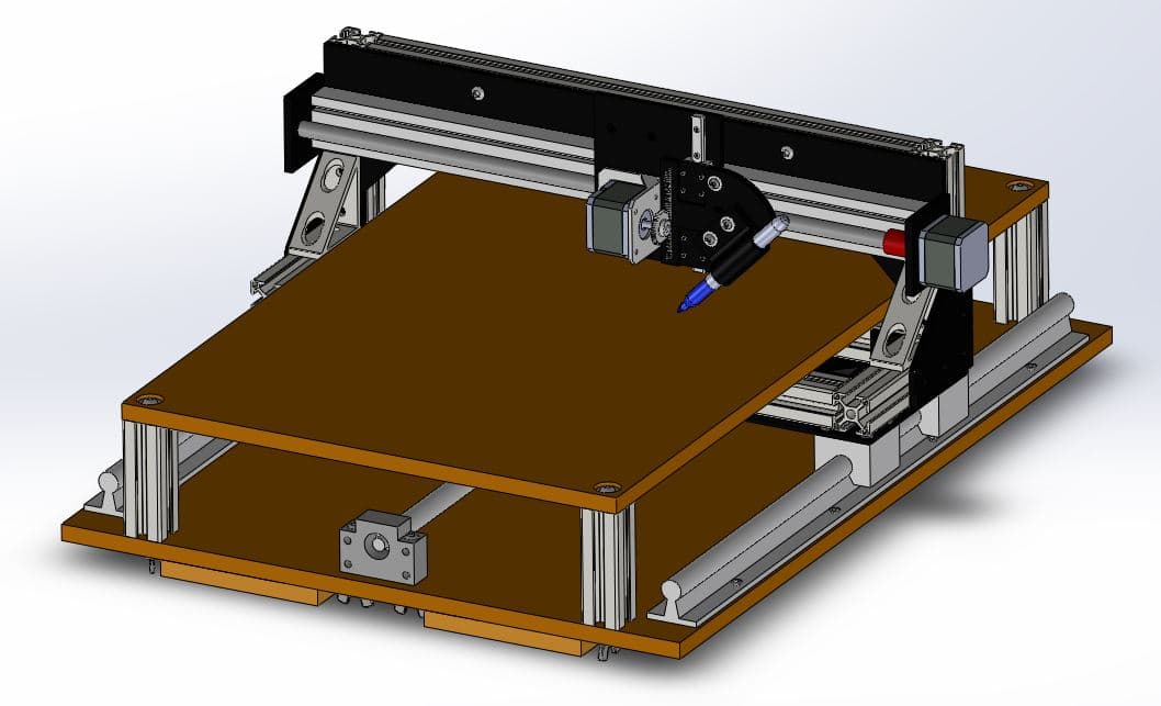
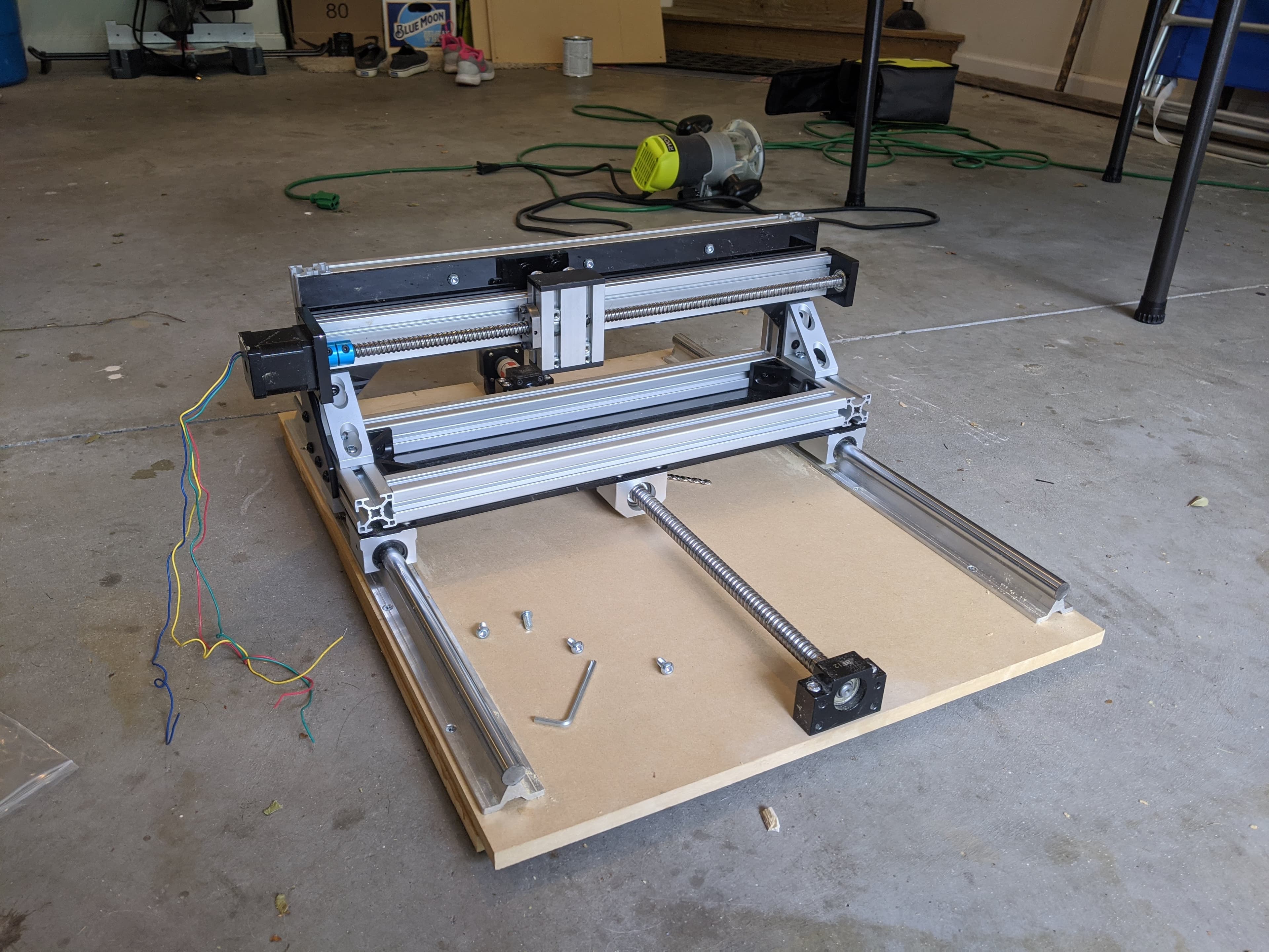
I fully designed the CNC plotter with the constraints of limited tools in mind. Because I was restricted to simple hand tools, the assembly was intentionally based on straightforward, modular components. The structure primarily uses standard aluminum extrusion, eliminating the need for additional cutting or machining after delivery. Particle board was selected for the platforms to ensure flat, stable surfaces critical for accurate plotting.
Laser-cut acrylic served as the primary structural interface between the aluminum extrusions. The acrylic sheets were custom cut with precisely located holes, allowing the frame to be assembled accurately and repeatably. Maintaining near-perfect alignment was essential, as the plotter’s control system depends on precise motion across three orthogonal axes. Using laser-cut acrylic provided a low-cost and highly effective solution for achieving this level of precision with limited at-home fabrication resources.
Build
Prototyping
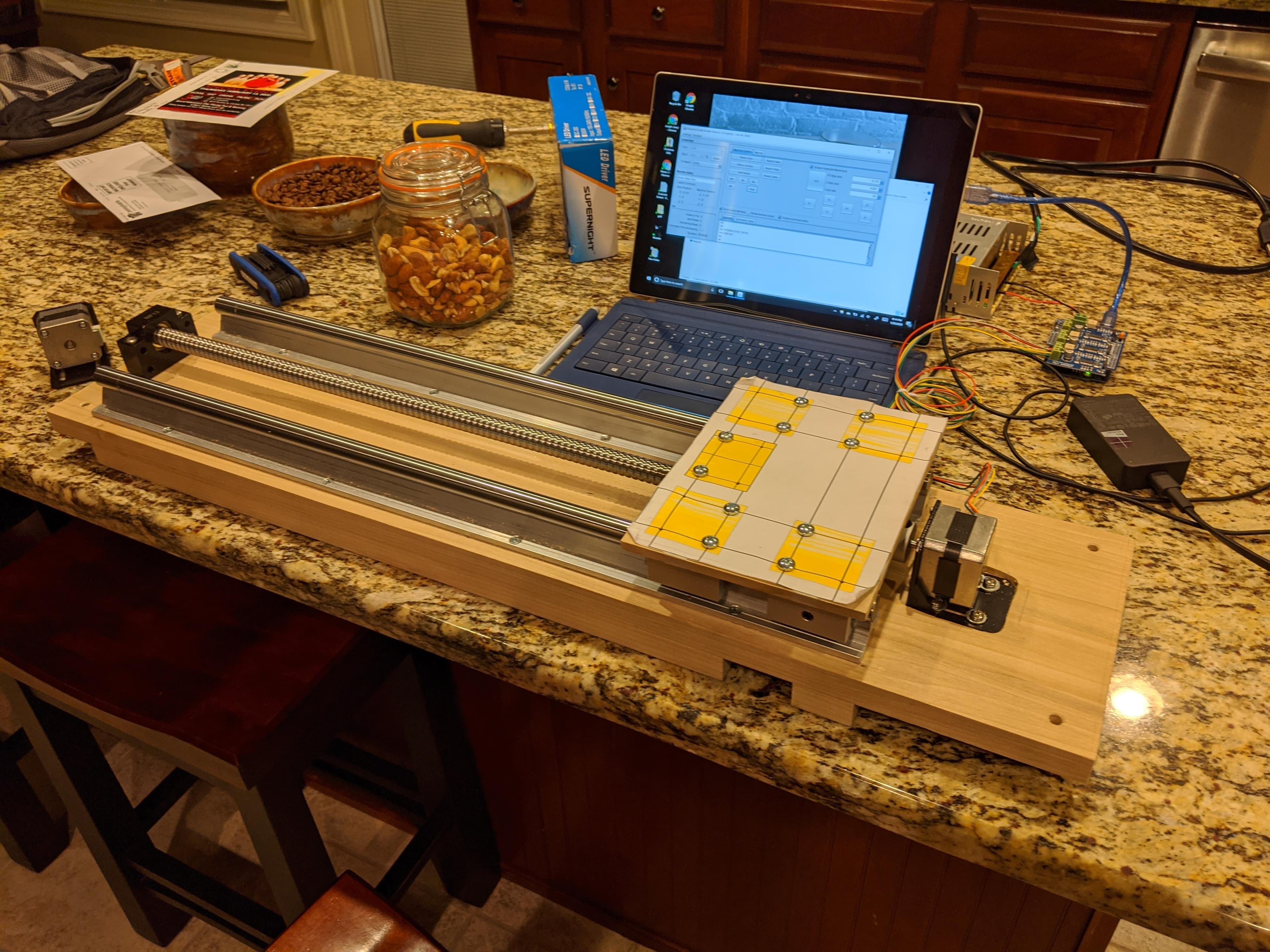
I evaluated several actuation options for translating each axis and ultimately selected a ball screw mechanism due to its high positional accuracy and reduced risk of slip compared to pulley-based systems.
Shown here is an early prototype built to evaluate ball screw control and overall feasibility. I initially had concerns that the ball screw might be too slow, prone to binding if the woodworking tolerances were not tight enough, or limited by stepper motor torque. The prototype performed reliably and validated the design approach, giving me confidence to proceed with the ball screw actuation strategy.
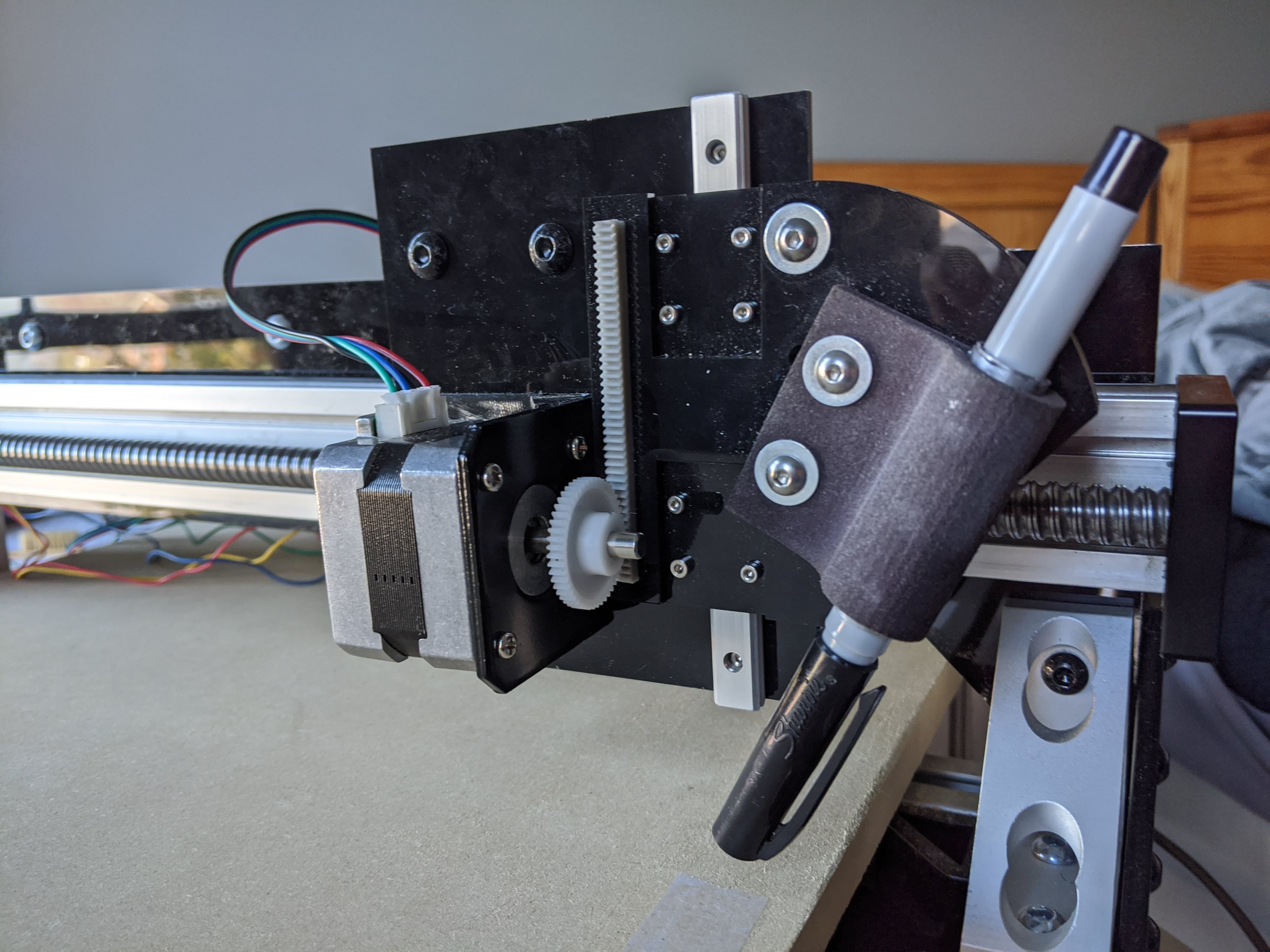
The pen holder concept I designed and produced using an SLA 3D printer turned out exceptionally well. The holder fits a Sharpie comfortably and clamps securely to a custom acrylic mount using two screws. A key feature of the design is adjustability: it allows the Sharpie to be set anywhere from vertical to a 45° angle of attack. I also designed the plate to accept a press-fit rack (for a rack-and-pinion system), which interfaces with a stepper motor and gear to raise and lower the Sharpie during plotting. This mechanism functions as the plotter’s Z-axis actuation system.
Custom pen holder
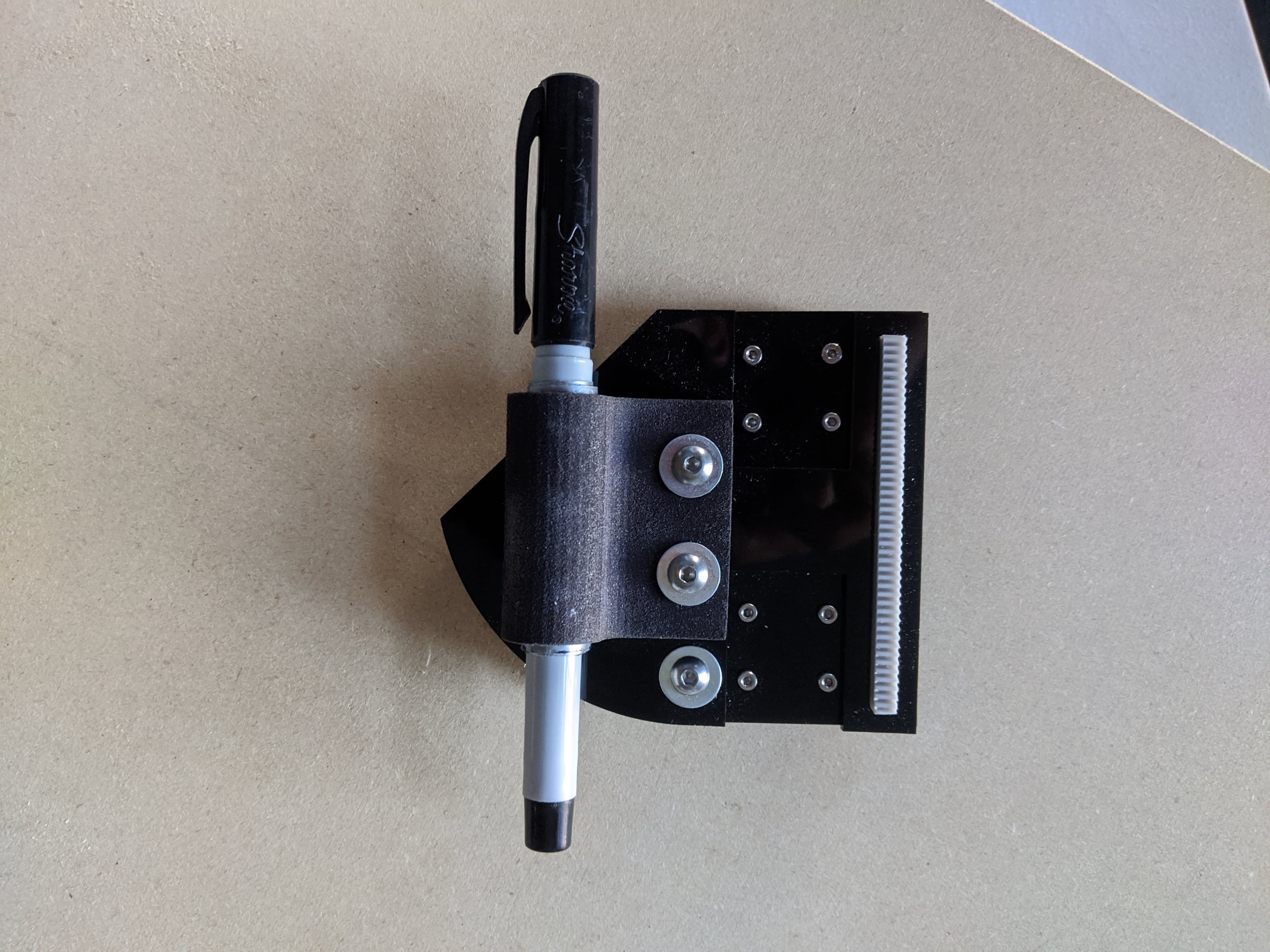
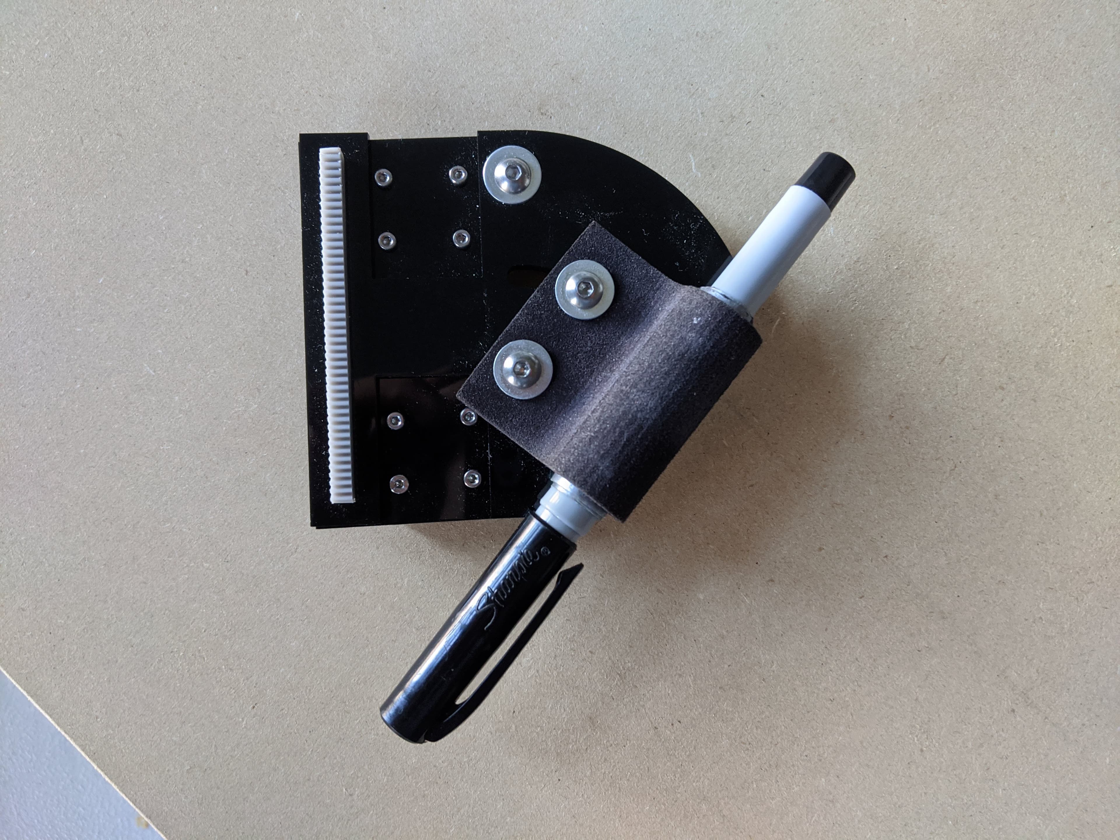
Z-axis actuator
Here, you can see a closer image of how the Z-axis mechanism handles pen-up / pen-down motion so the plotter can move between strokes without dragging ink.
Software
Programming
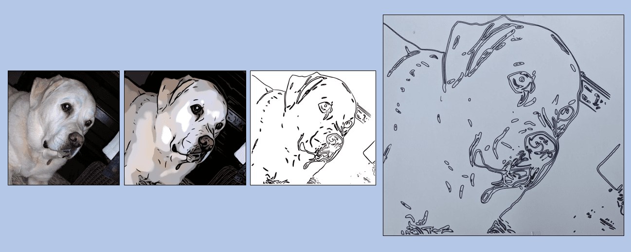
On the software side, I wrote a few simple programs that could take a photo, apply some simple filters to smooth minor features and emphasize key contrast edges, detect those edges, and convert those edges into g-code. Here, I have a few screenshots of this pipeline.
Results
Plotting
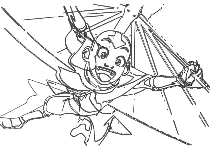
Once the tuning was dialed in, the plotter could reliably reproduce edge-detected portraits as clean marker drawings. Here is a gif of the plotter making a drawing of Aang from Avatar the Last Airbender.
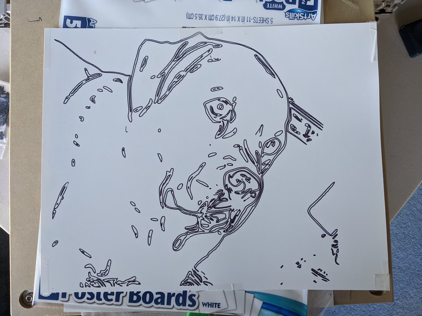
Here the plotter is drawing my dog Pippin. You can see a fuller video of this here.
Wrap-up
Takeaways
One persistent issue I had with this design iteration was that the stepper motor for the z-axis would burn out. As a result, the plotter did not always lift up the sharpie between strokes. Instead, the marker would stay pressed on the paper, and it would generate lines connecting features that should have been isolated from each other. I once thought I would someday like to upgrade the z-axis motor to be more robust to address this issue. More than likely, I won't ever do this! I would like to embark on a whole new cnc project that is more capable, now that I have grown my machining resources and skillset!