Design and Deployment of a Remote Aerosol Research Facility
Powder Mountain, Utah • Mechanical design • Project execution • Field deployment

Summary
I led the engineering design and field installation of a 30-ft aerosol inlet for a remote mountaintop lab at Powder Mountain, Utah, and I delivered the system on a four-month timeline. For the winters of 2025 and 2026, this inlet will be supplying ambient mountain air to multiple instruments that are collecting data to study the impacts of cloud-seeding in the Wasatch Range.
I collaborated with aerosol scientists to iterate quickly on requirements, and I maintained an active and respectful relationships with our University machine shop to refine drawings for manufacturability so parts could be produced reliably and with our rushed schedule. I also designed the support and anchoring approach to keep the ~150-lb inlet stable in harsh winter conditions and wind speeds above 100 mph.
During installation, I worked closely with local technicians to install the inlet to the roof of the container, and I physically built, aligned, and fastened the inlet and support structure, as per my design specifications. Of course, as is expected with any fieldwork in the mountains, I was constantly needing to quickly react and solve unexpected field issues quickly to keep the system safe, serviceable, and sampling-ready.
Skills Required & Applied
- Mechanical system design (SolidWorks 3D & 2D)
- Familiarity w/machining (mills, lathes, CNC, welding)
- Machine ship coordination (DFM, quotes, revs)
- Structural load-path thinking (wind/snow stability)
- Constraint-driven engineering (landuse, time, $$$)
- Hardware selection + BOM planning
- Field installation (powertools & troubleshooting)
- Communication (shop <-> science team <-> on-site)
Inlet build highlights
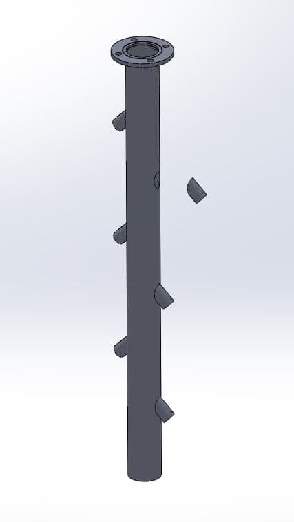
Custom manifold design for high-integrity aerosol sampling
The inlet manifold was designed to deliver ambient air to multiple aerosol instruments while minimizing particle losses. The concept intentionally mirrored proven research inlets at the University of Utah (William Browning Building rooftop inlet) and Storm Peak Laboratory, but was adapted for a remote container deployment and improved flow distribution. A key enhancement was an alternating outlet pattern that spreads flow more evenly—improving delivery efficiency across ports.
Because this project ran on a tight 3-month timeline, I partnered closely with a machine shop to rework the original inlet design for fast, repeatable manufacturing. Instead of complex fixtures and manual tooling that could introduce obstructions to inlet airflow, we used custom precision-machined inserts that could be easily welded to the pipe. That approach was time efficient, while also mitigating risks of human error during the machining process and providing improved dimensional control.
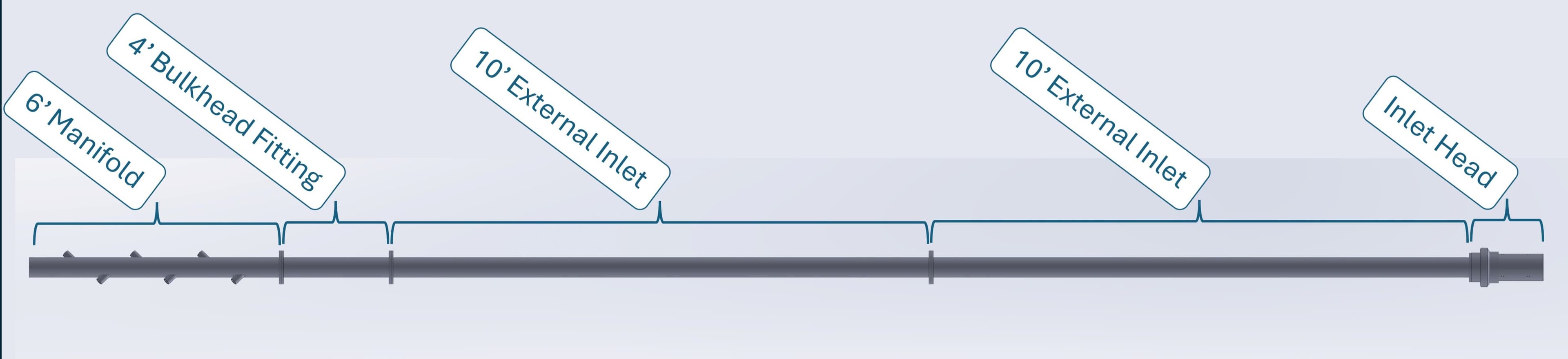
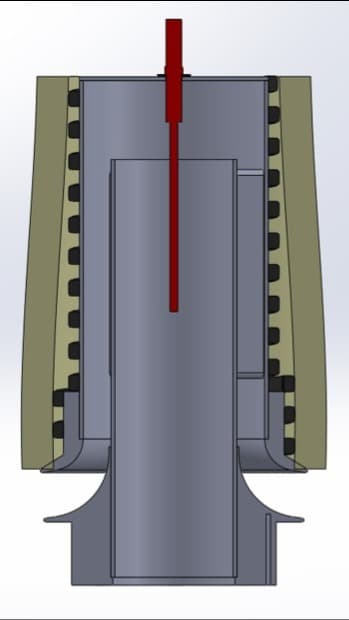
This full design assembly view shows how the inlet was engineered as a modular system. The manifold distributes flow inside the container, while a roof bulkhead fitting both seals the penetration against snow/ice/water and supports the vertical load of the inlet. Above the roof, two modular 10-foot inlet sections extend the sampling point beyond local contamination near the container and into cleaner atmospheric flow (and cloud/fog conditions). The inlet head pulls in ambient air and incorporates heating features intended to prevent icing during winter operations.
Lab support assembly
Support strategy: concept iteration under real site constraints
The 30-ft inlet weighed approximately 150 pounds, and 20 ft of the inlet needed to extend above the roof the container. Furthermore, the container would be stationed on a summit of Powder Mountain Ski Resort, where winds have been recorded above 100 mph. Beyond the structural needs, the inlet needed to be installed in an appropriate position, so that instruments could be placed around the inlet, as close as possible, to minimize particle loss.
As the lead on this body of engineering work, it was necessary to communicate concepts to the larger team of managers and scientists effectively using SolidWorks modeling. I first made detailed measurements of the shipping container and the instruments that would need to be installed. I then iterated through several support concepts, as per my own independent research and by connecting with local millwrights and several mechanical engineers within my network to gain their respective insights.
Initial approach: leverage known Rohn tower installation practices to support the inlet. However, concrete footings were not permitted on our site location
Constraint-driven iteration: Generated a lightweight ballast system that utilized the fork ports at the base of the container
Final strategy: self-contained anchoring to the container.
Ultimately, the team decided the guy-wire system anchored directly to the container would be most appropriate. That decision created three urgent engineering needs as the schedule tightened: (1) a container anchor system to hold the guy wires to the container's four corner castings, (2) safe, non-slip clamp system onto which the guy wires would fasten to the inlet, and (3) a vertical load support solution, since guy wires stabilize laterally but would not carry the inlet’s weight.
Challenge 1: anchoring guy wires to the container
The anchoring approach needed to convert high lateral loads from wind into a clean load path from the guy wires and through the container’s corner castings. The corner castings were quite bulky, so a typical shackle system was not possible. The final hardware was effectively a modified U-bolt, designed to be simple and strong and needing minimal machining work.
a simple U-bolt with a custom-machined stainless, half-rod to reduce any stress concentrations on the anchor.
the installed anchor on one of the corner castings
Challenge 2: attaching guy wires to the inlet pipe
Because the guy wire support system was not the original plan, the inlet was not inherently designed or built to interface with guy wires. I designed and built a custom pipe-clamp-mount, that would hold tight to the inlet diameter and attach to the four guy wires running to each corner casting. Because the inlet would be in cold and windy environments, I had beads of weldement added around the circumference of the inlet to mitigate any risk of the clamp becoming loose and slipping down the inlet.
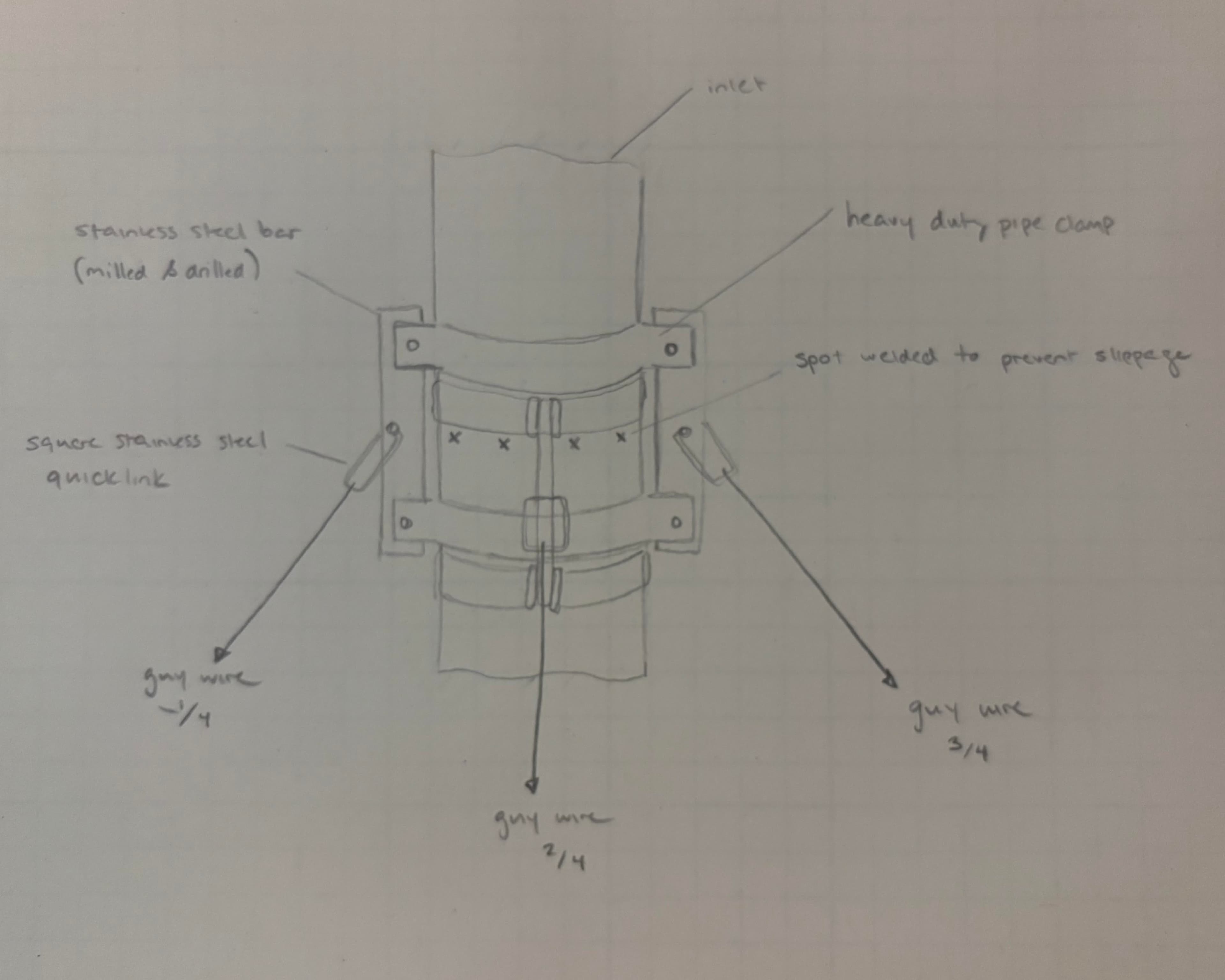
an initial sketch of the clamp idea before detailing the concept to CAD
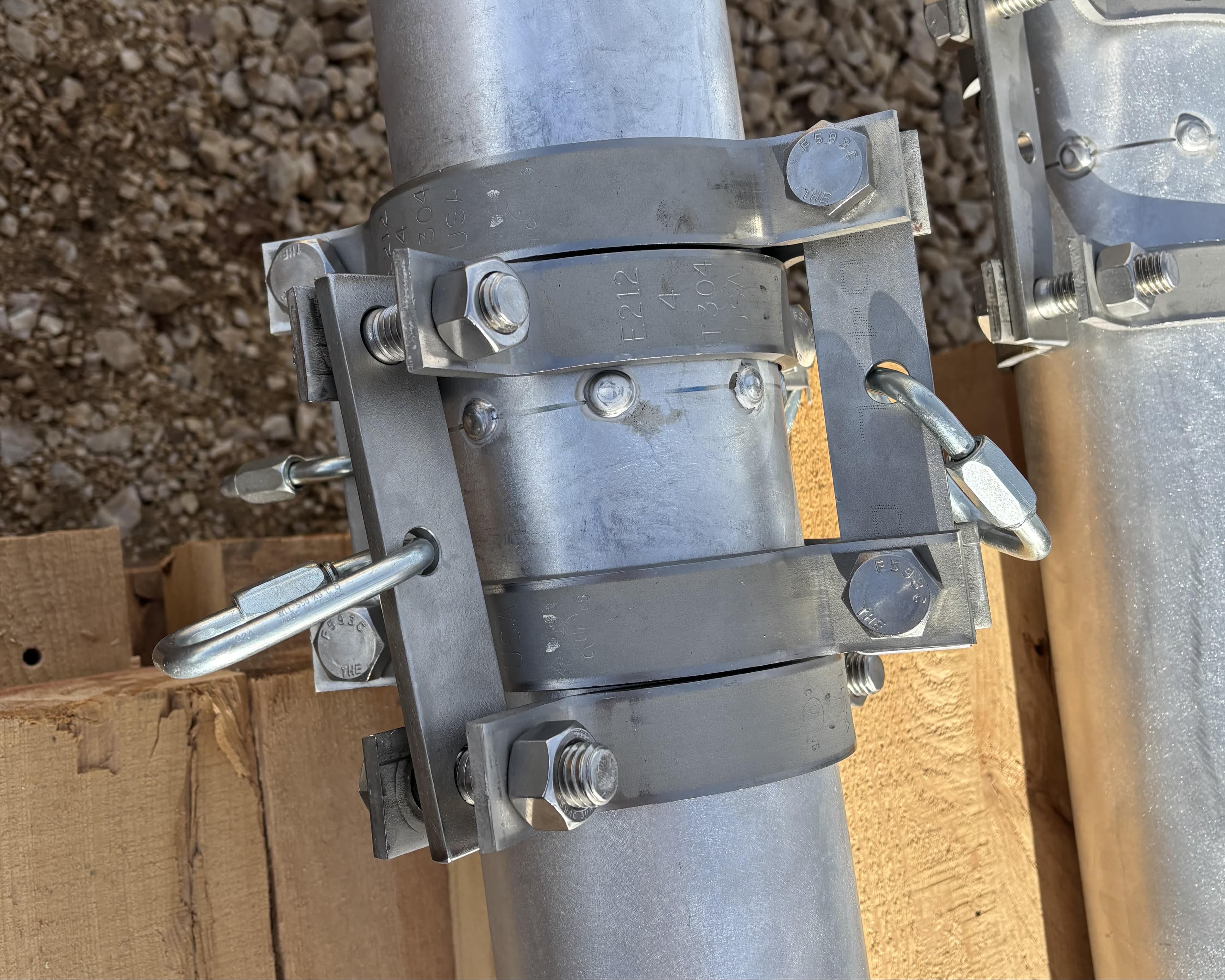
a completely installed prototype of the clamp-mount and weldement beads on the inlet
on-site, we found that we could simplify the design to reduce the weight of the clamp system, which is what is pictured here. Success!
Challenge 3: supporting inlet weight + sealing the roof penetration
In reaction to the new challenge of needing to support the weight of the inlet and downward force of the tensioned guy wires, I quickly designed and rush ordered a custom seal and support assembly. I ensured the assembly only required basic machining practices and could be manufactured and installed quickly, but also meet appropriate structural requirements.
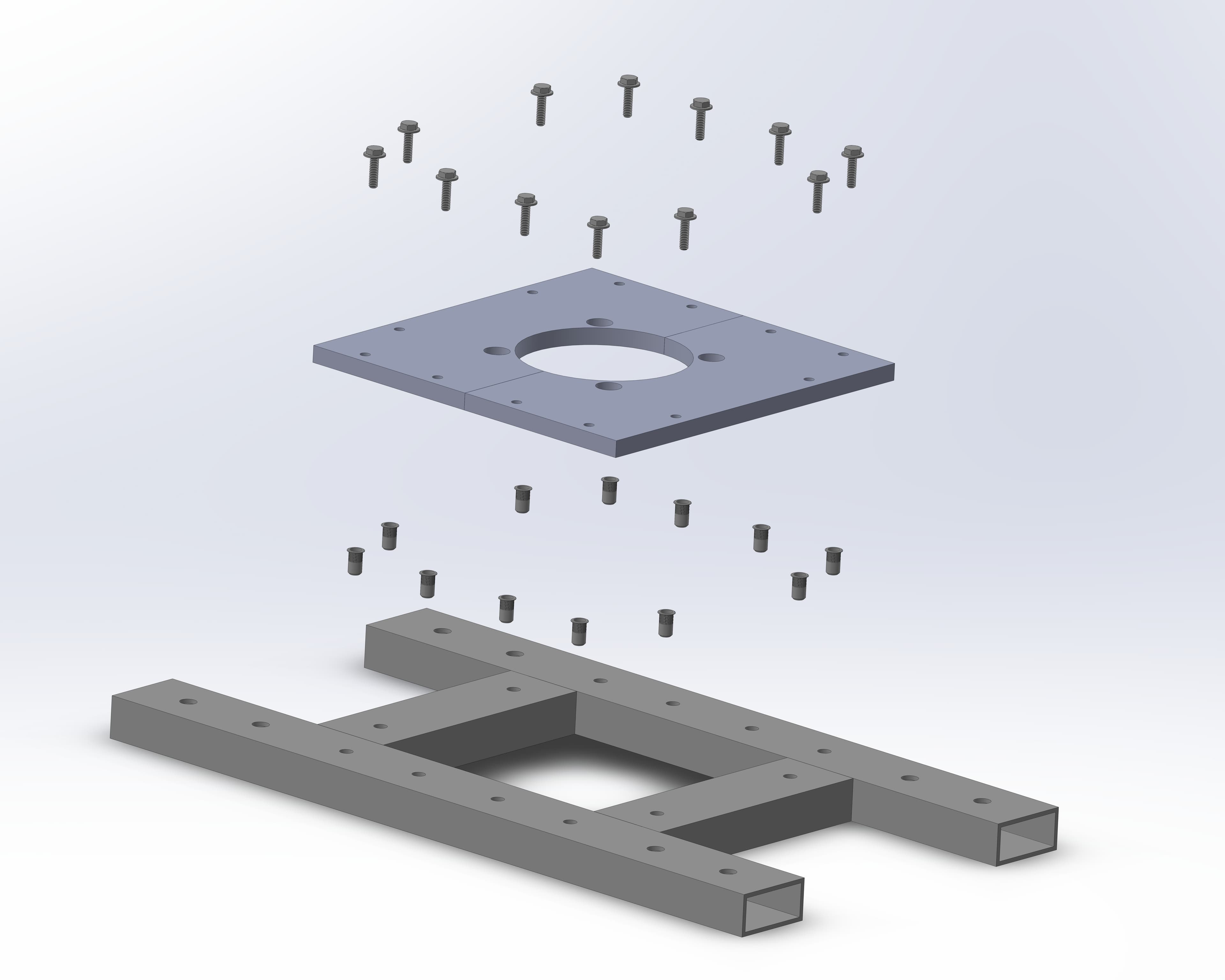
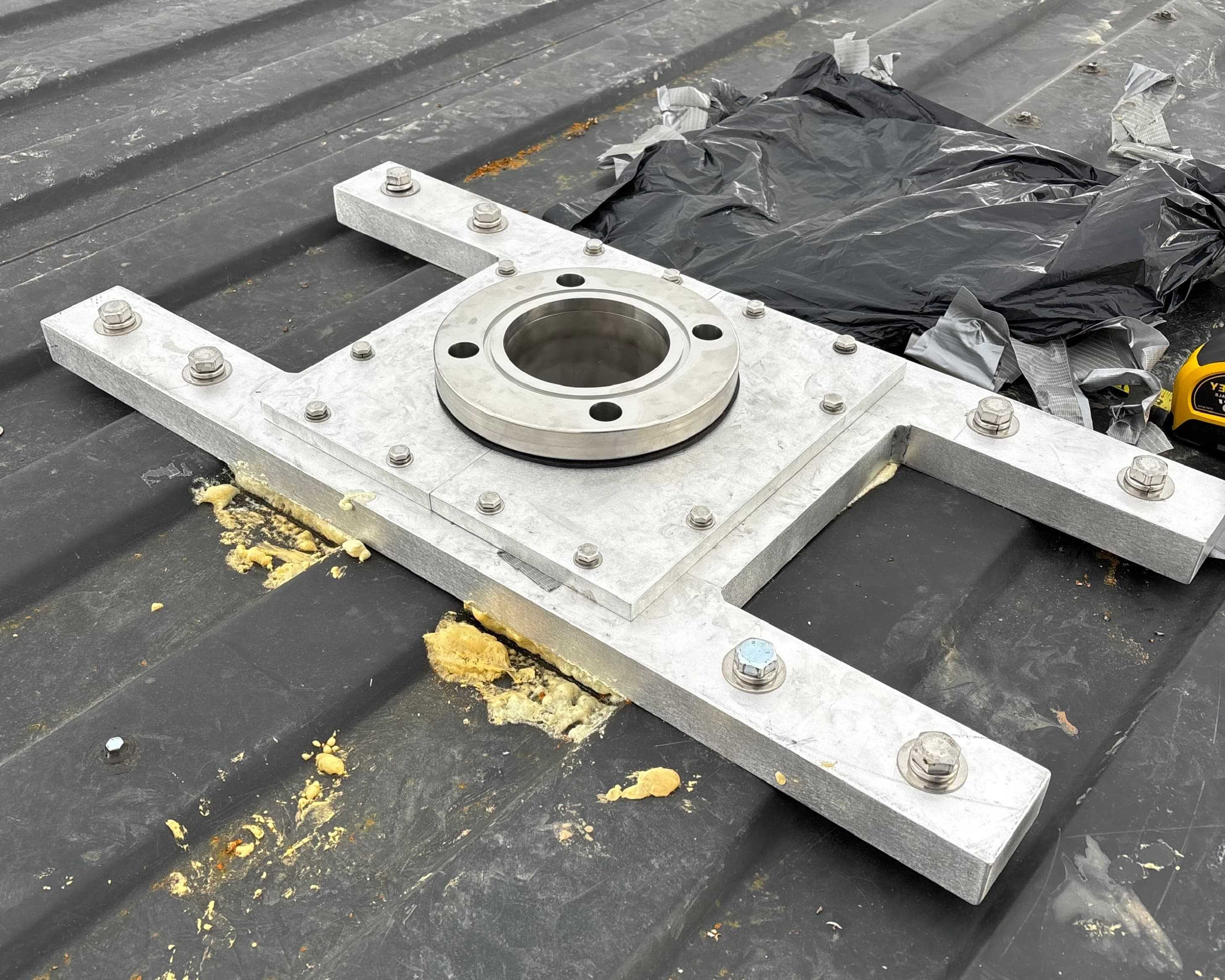
dual-purpose design: weather seal + a support surface for the bulkhead flange to carry vertical load.
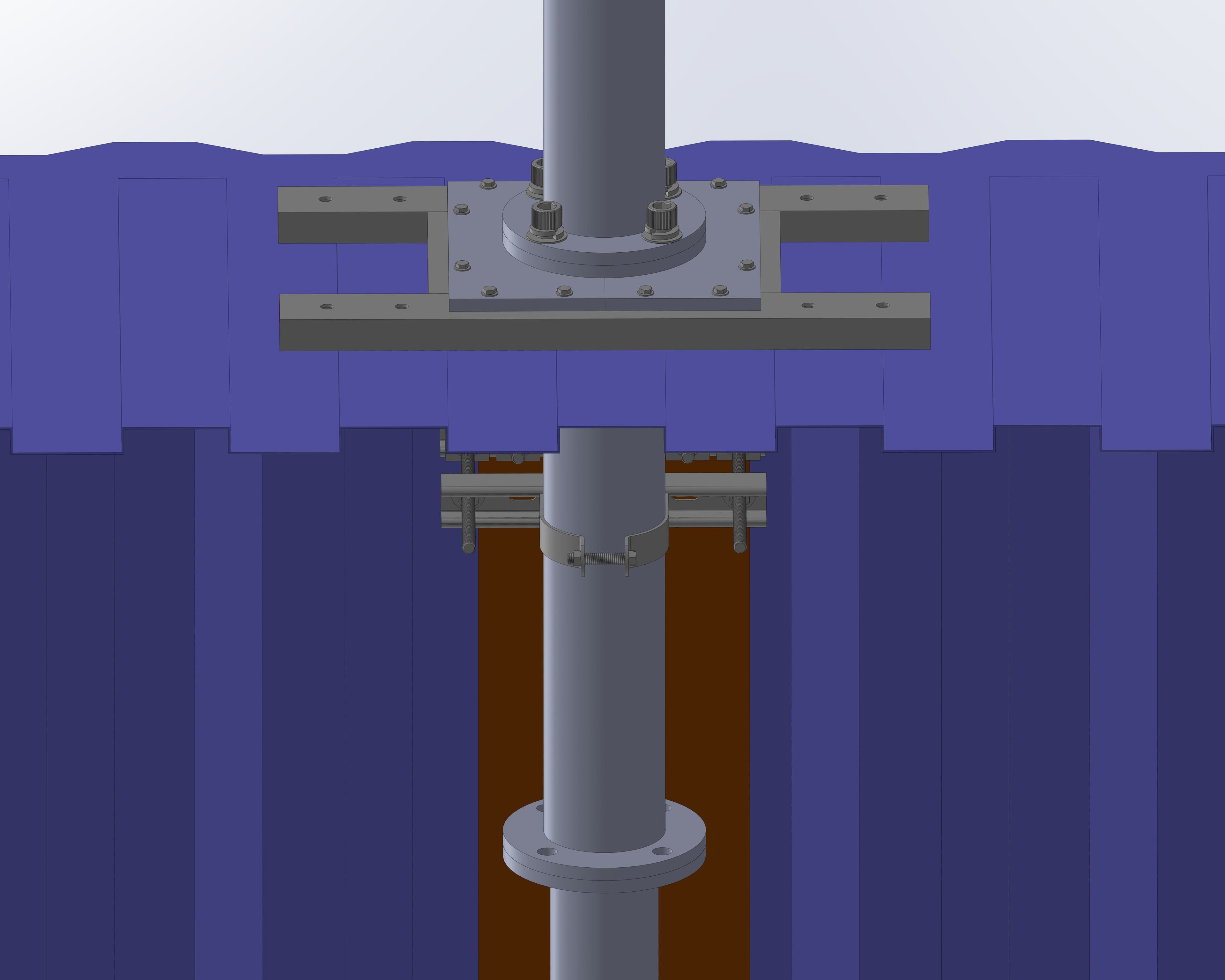
mock-up/fit-up: confirm interfaces w/rest of modeled lab before field installation to reduce surprises under time pressure.
On-site execution: align, fasten, and seal while maintaining inlet alignment.
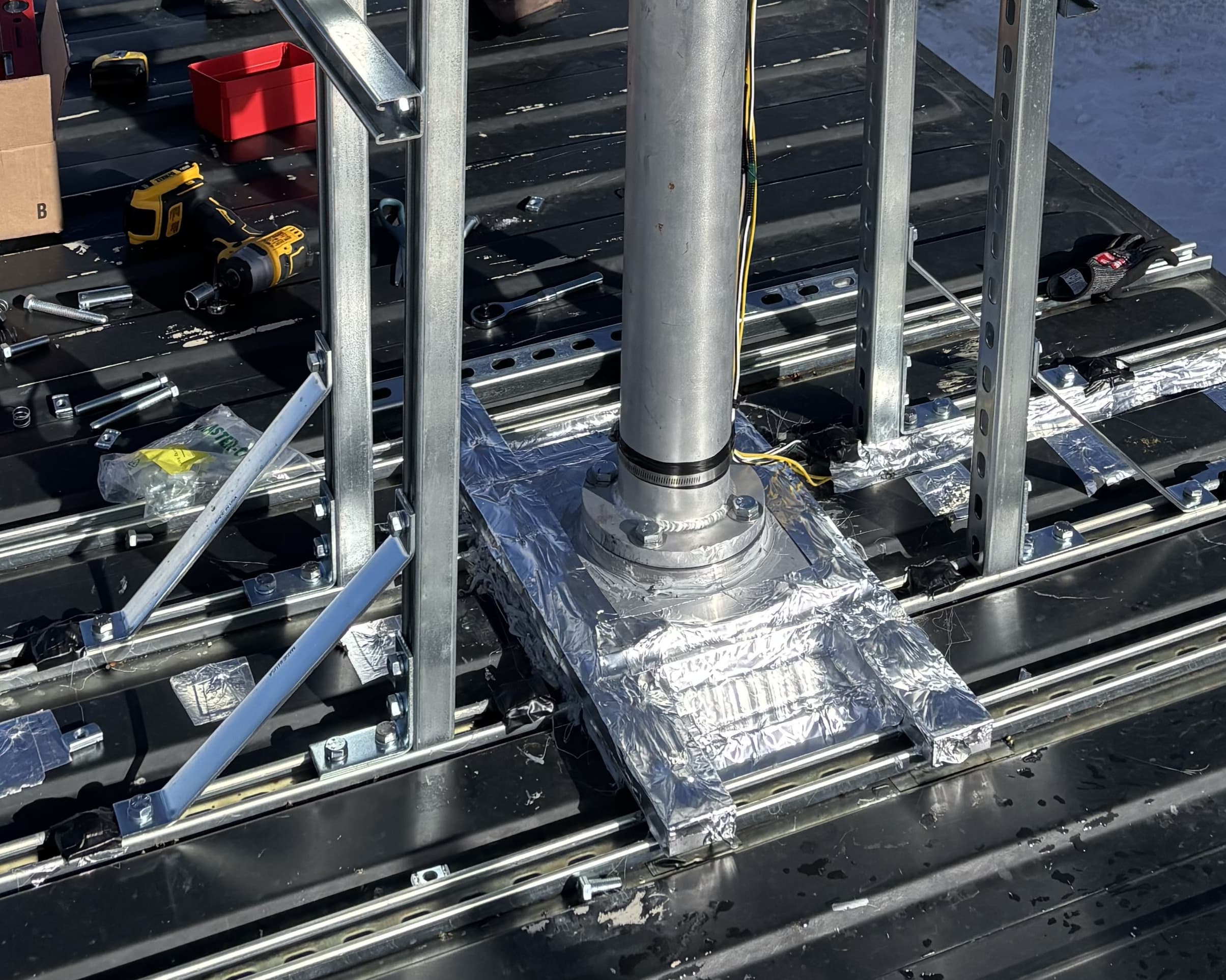
final install: robust weather sealing and a reliable load-bearing interface.
Additional responsibility
Heated Inlet Concept Generation
I also developed a heating approach aligned with aerosol inlet standards (e.g., WMO-GAW / ACTRIS-style guidance) to prevent icing while protecting sampling integrity. Although we ultimately did not execute this design initially—because tariffs and supply chain disruptions pushed the preferred heating elements to long lead times—I delivered a complete concept and analysis that could be implemented later without redesigning the system from scratch.
sillicone heaters line the length of the inlet, housed in 3/4-in fiberglass insulation
at the inlet cap, a thermocouple provides a temperature reading of the incoming air, so the sillicone heating power can be adjusted
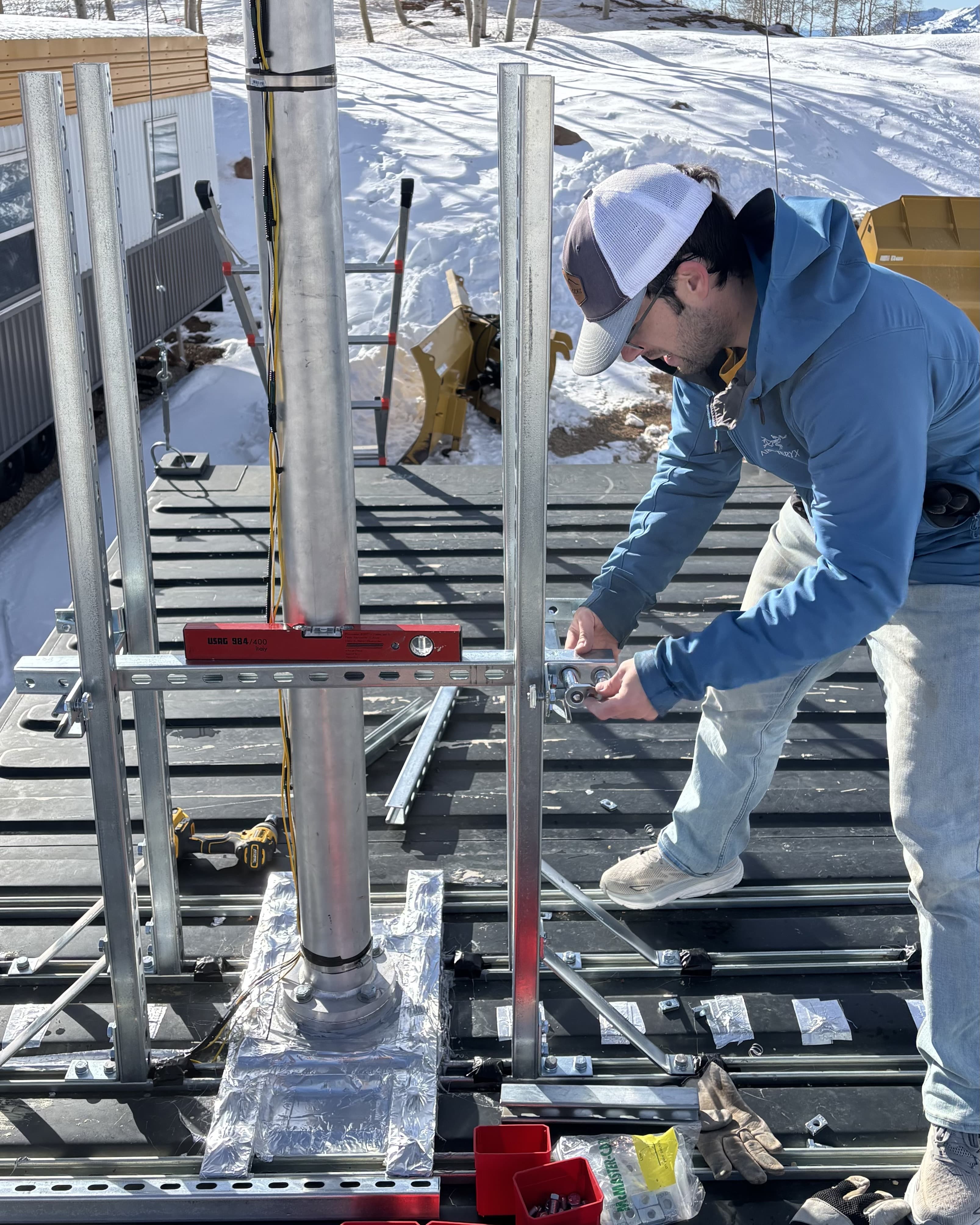
Field installation
On-site build, alignment, and commissioning
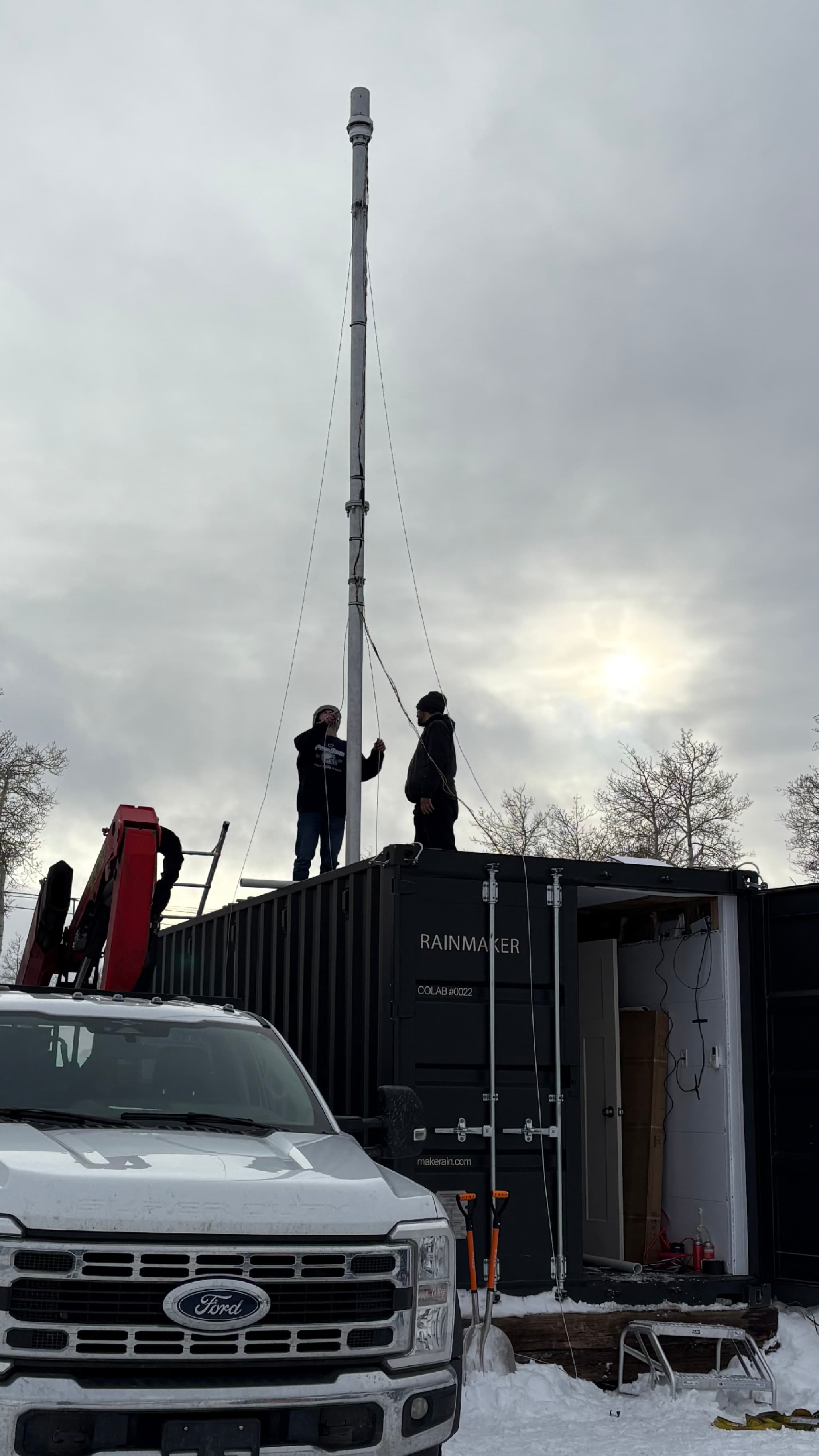
The field work required fast, high-quality decisions in winter conditions. Key mechanical challenges included positioning and aligning the inlet, sealing the container, validating and reinforcing the stability of internal and external support structures, plumbing the air to an outlet of the container, positioning the instruments within the container around the inlet, and keeping the container sealed and serviceable between site visits while scientists began commissioning their instruments in parallel.
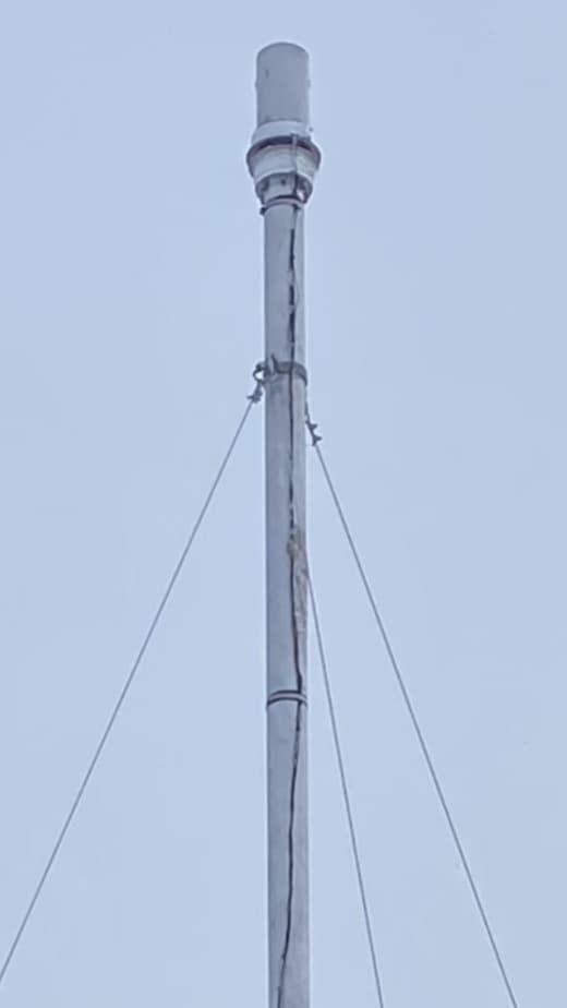
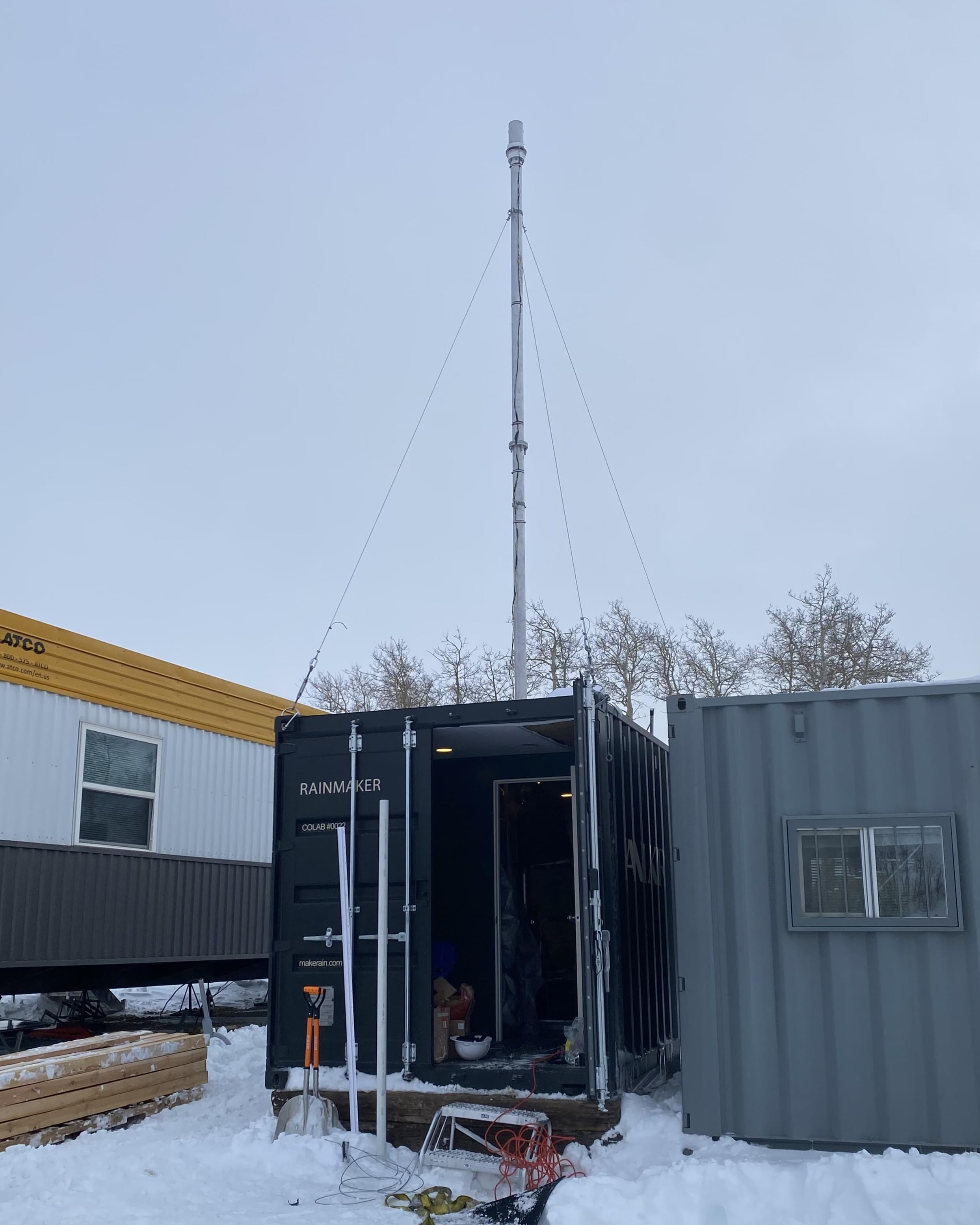
Here, I have included two photos of the inlet after it had been lowered by a crane to the roof of the mobile lab.
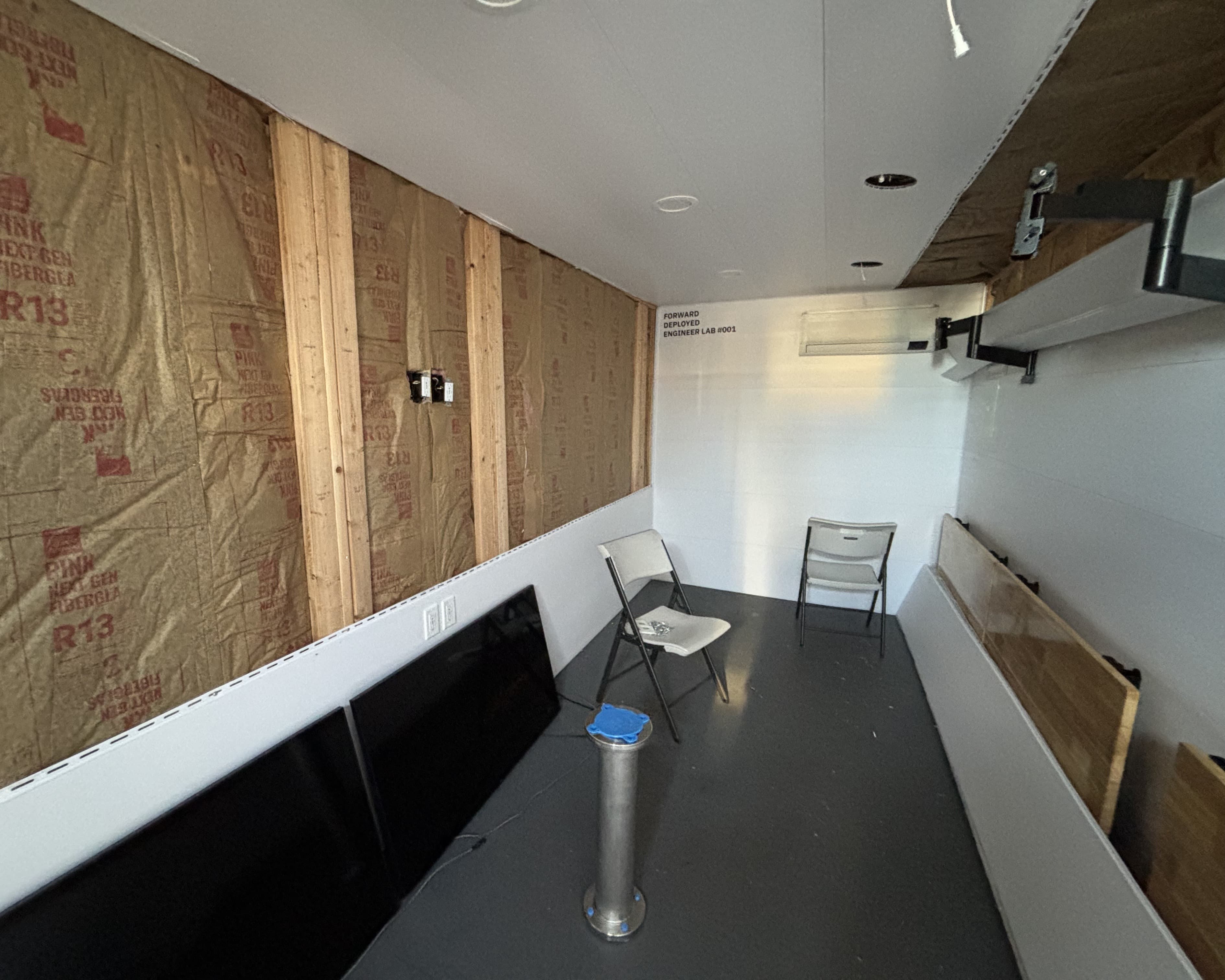
In parallel to the inlet being designed and built, I helped transfrom the shipping container into the serviceable lab that it is today: planning instrument placement, cutting penetrations, crafting unistrut framing, routing the inlet through the interior, and building an ergonomic layout that supports both performance and maintenance.
a virgin shipping container before any lab-related modifications
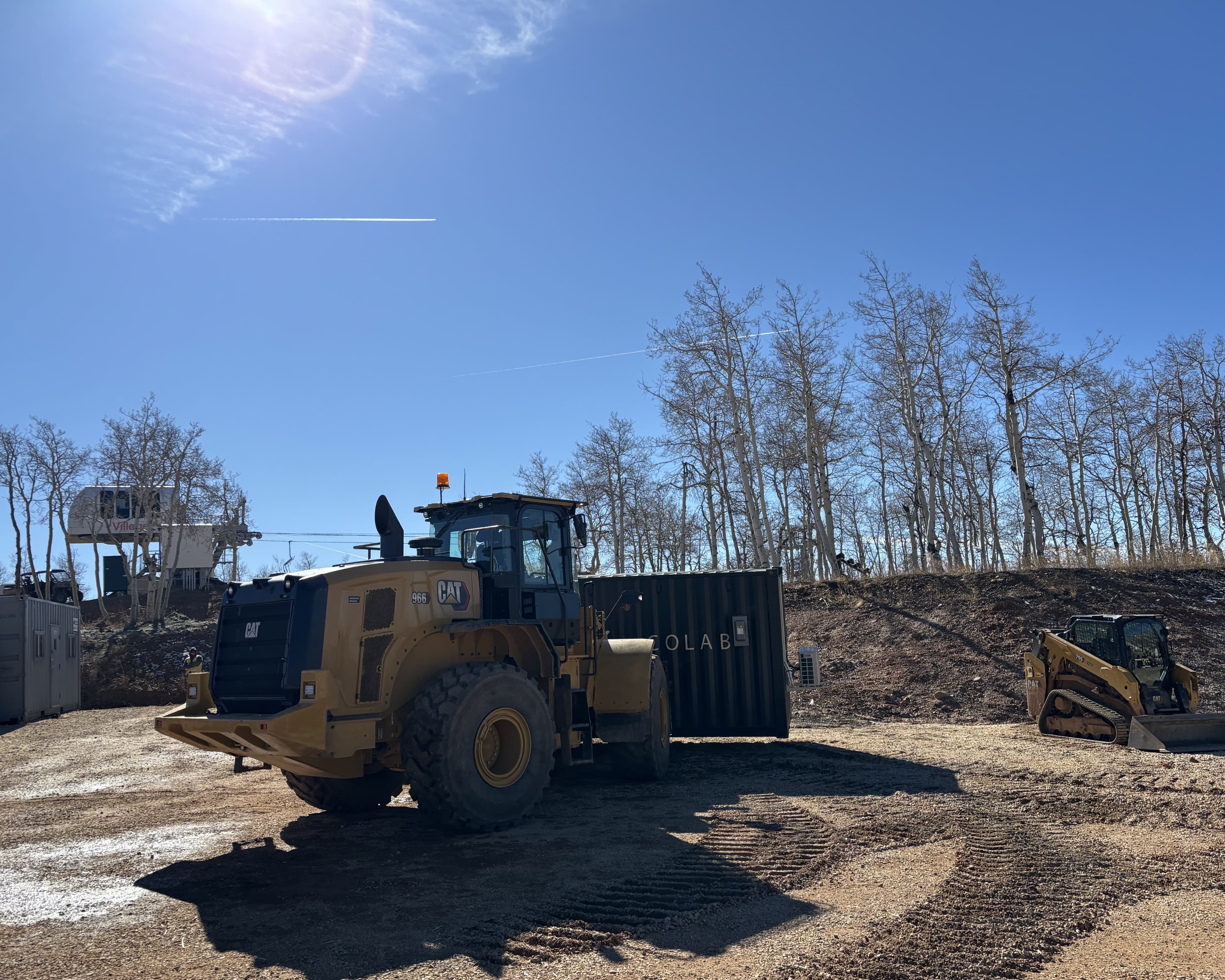
lab being transported and leveled to its allocated area
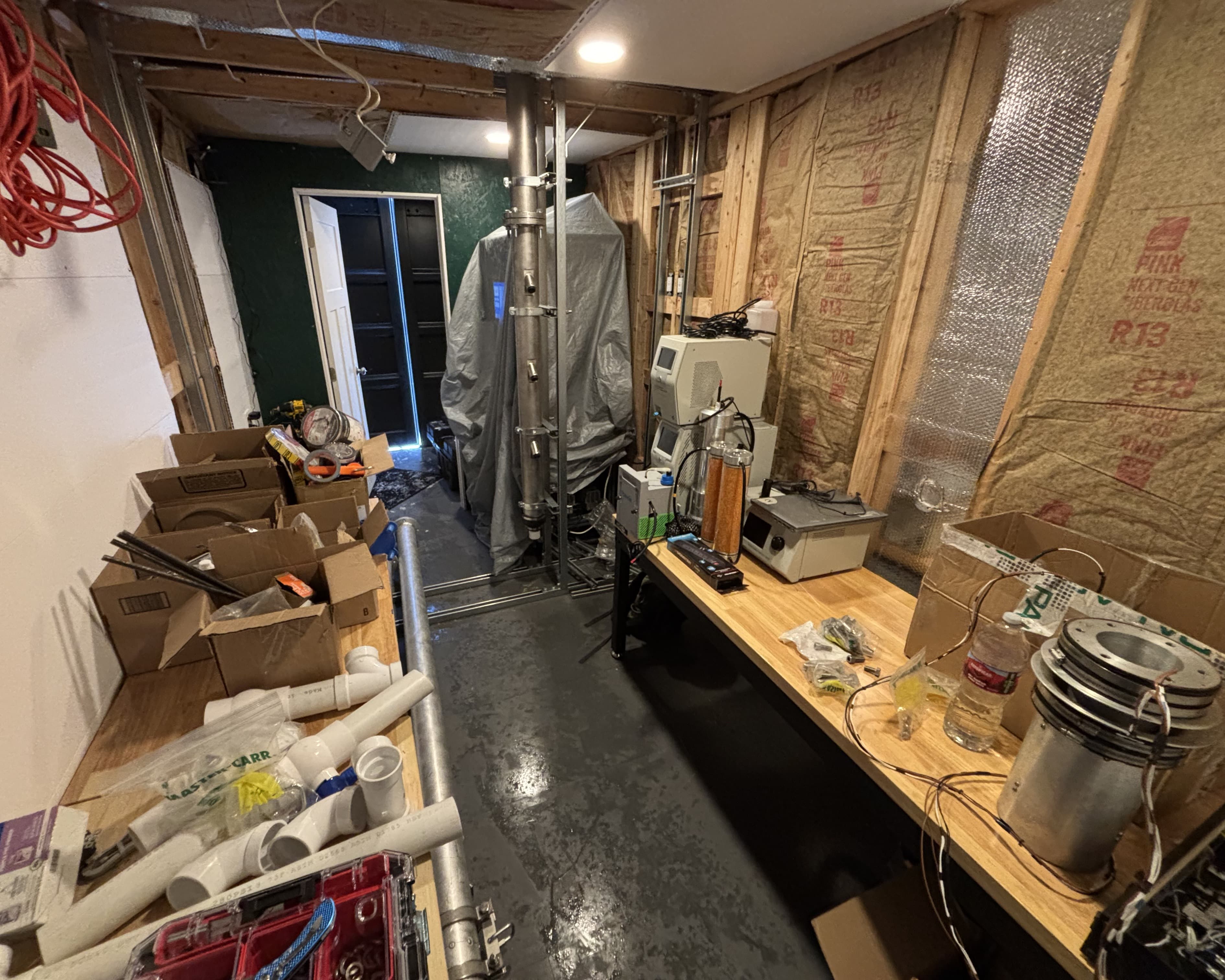
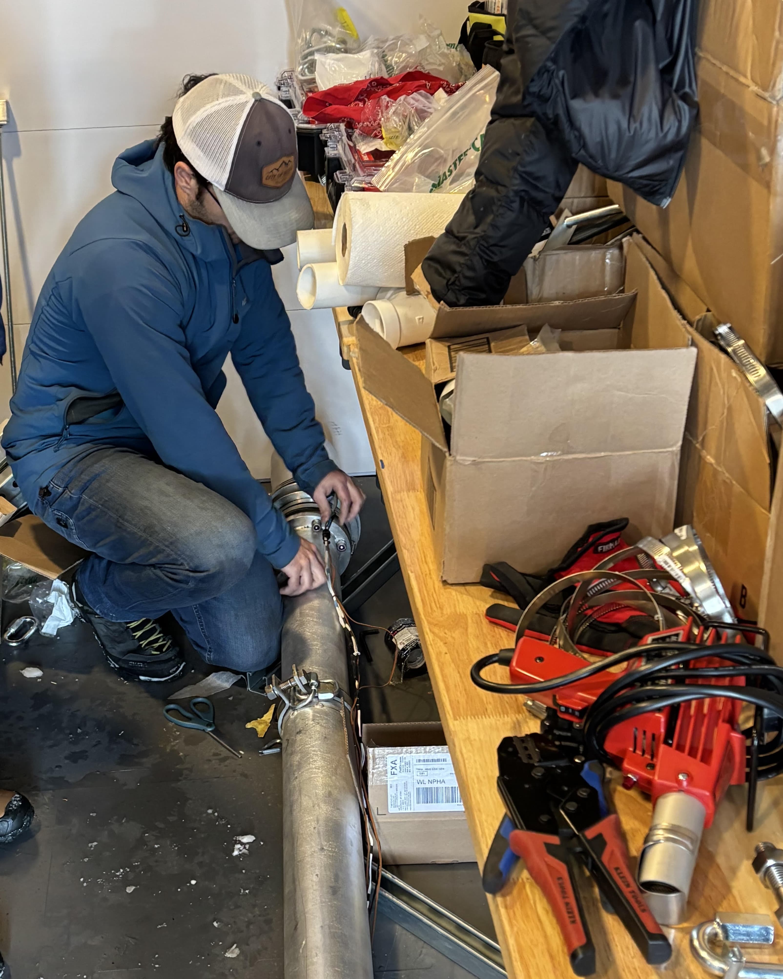
a view of the messy inside of the lab being built and organized
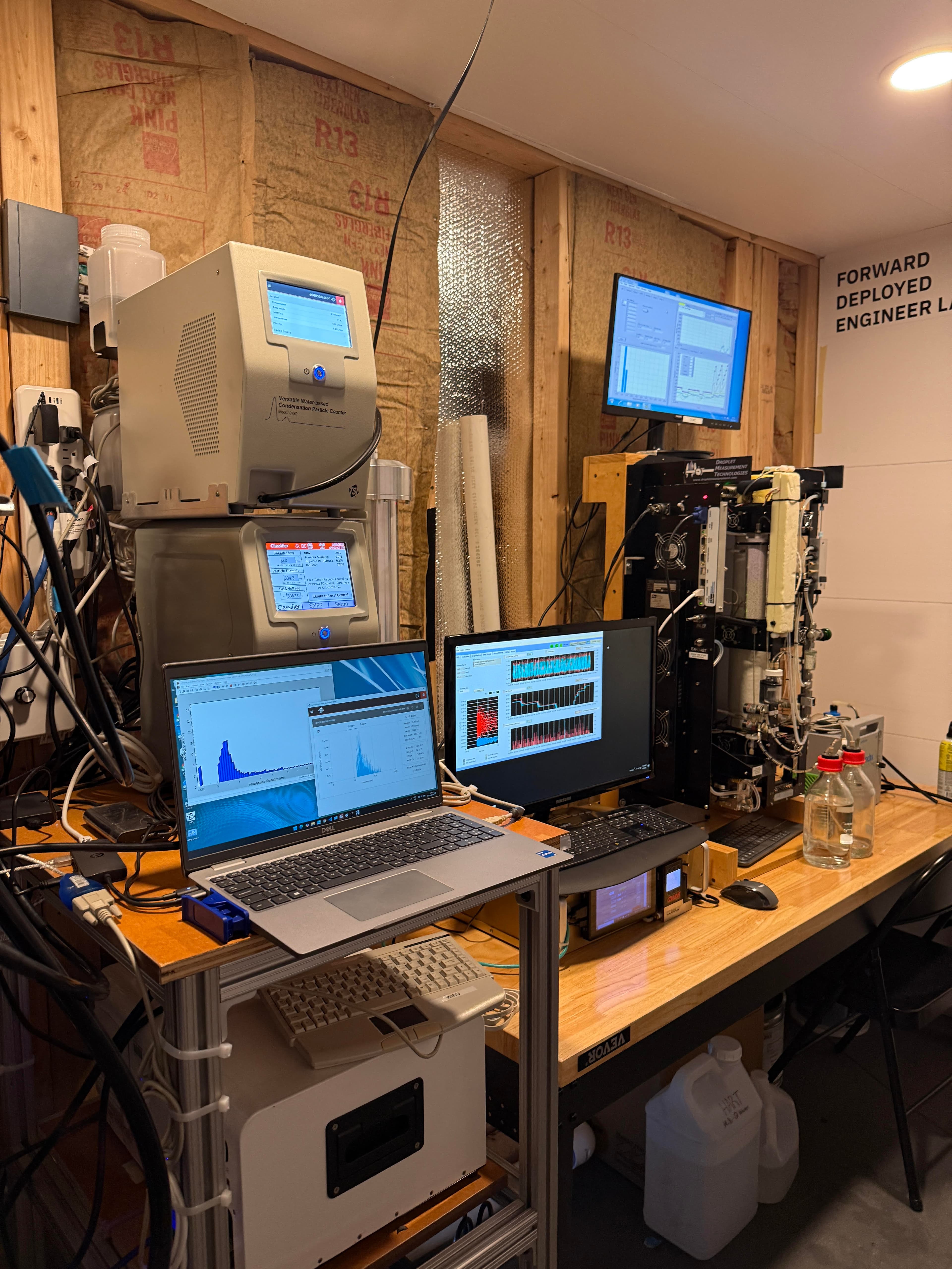
a view of the instruments that were commissioned (by others) and using air fed by the inlet
Team Communication
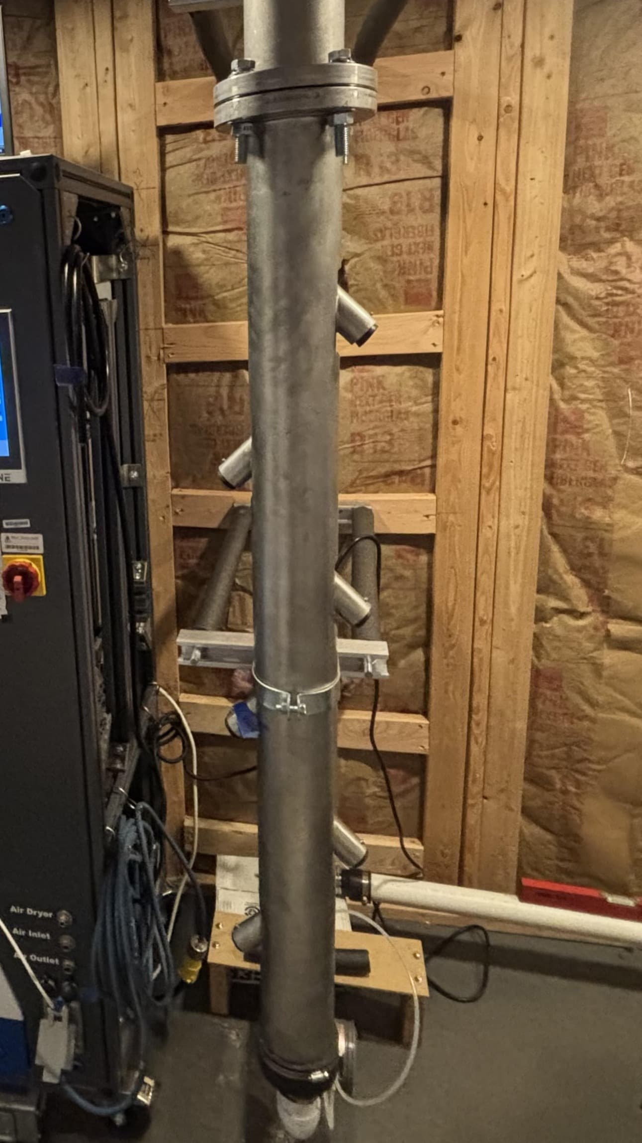
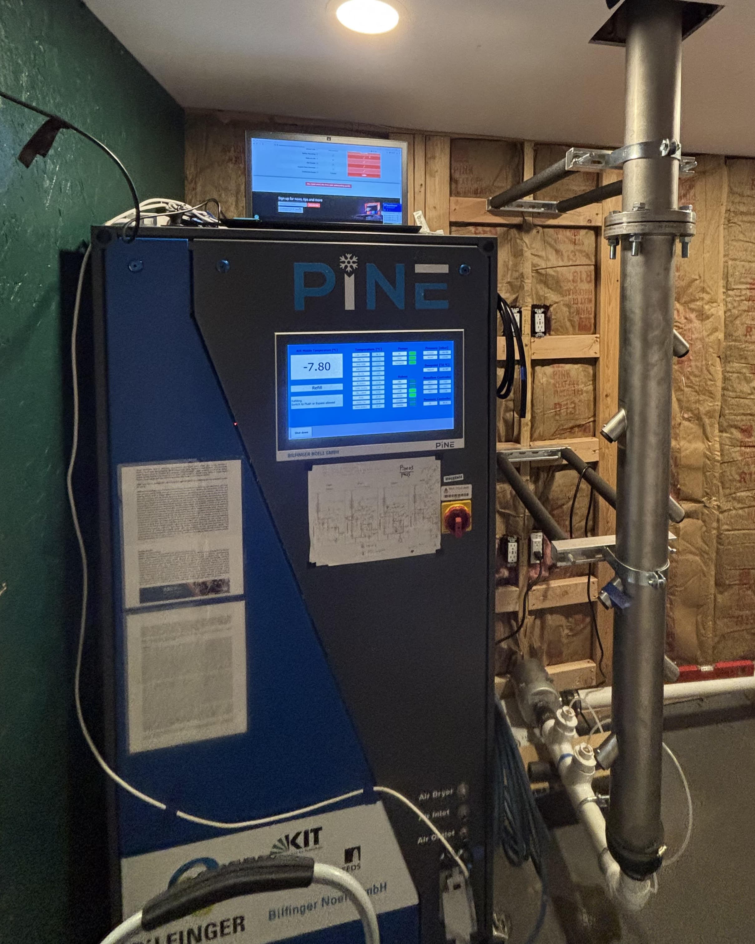
Shown here is an early installation of an instrument that measures ice-nucleating particles, positioned near the base manifold of the 30-ft inlet. Close coordination with scientists was essential to ensure that on-site engineering decisions aligned with instrument requirements as commissioning began in parallel.
In the early stages of the project planning, I also led many of the discussions where I shared possible floorplans for the lab using SolidWorks and the team decided how they wanted instruments and the inlet positioned in the lab.
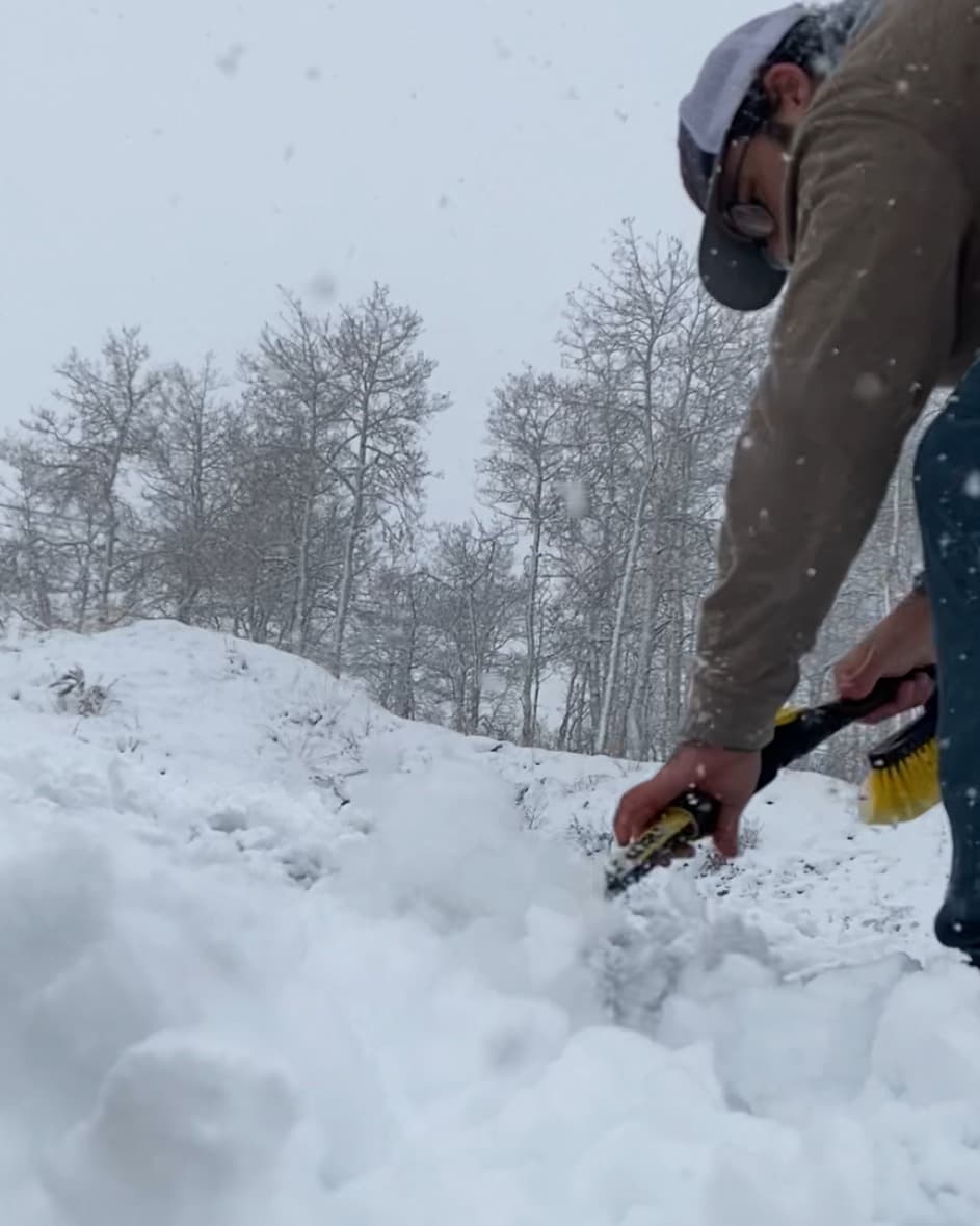
Random Fieldwork Highlights
Here are some photos showing day-to-day field work during installation, including winter conditions, on-site iteration, and hands-on construction details.
References
Facilities & inspiration sources
The manifold concept drew from proven inlet designs used at established atmospheric research facilities, then adapted for a container-based, remote deployment and improved for efficient multi-port flow distribution and manufacturability.